I recently published a series of YouTube videos building block diagrams outlining the logical structure of NSX-T Data Center infrastructure. This was based upon NSX-T version 2.5.1. In this blog, I’ll recap the three videos which you can view on my YouTube channel.
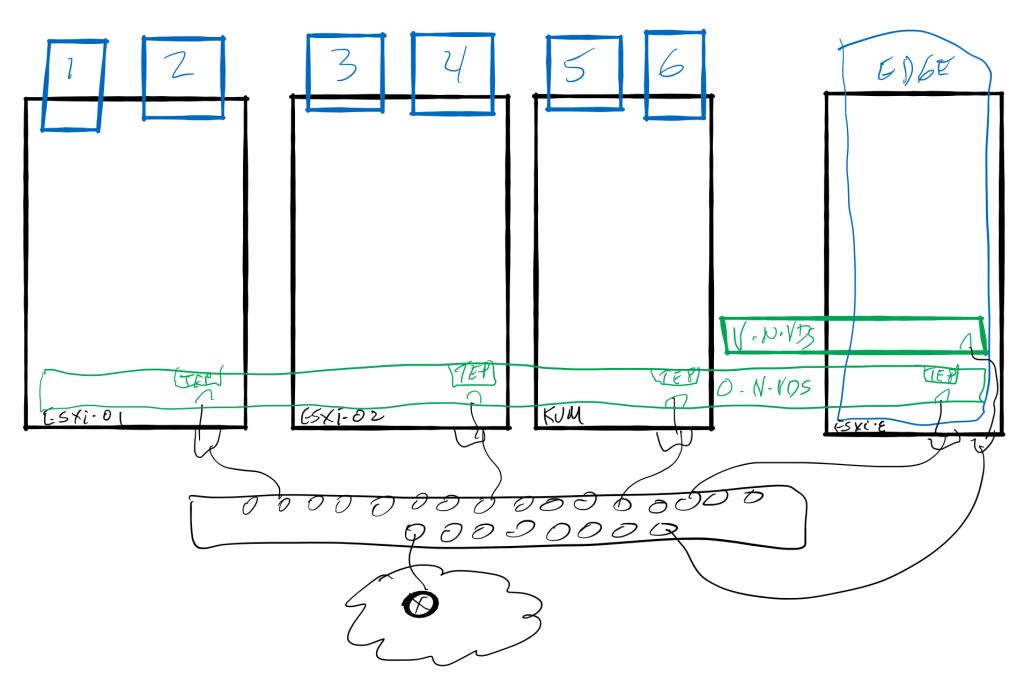
In the first of this series (volume 2, number 1) I described the preparation of the transport nodes. This process installs the NSX bits onto the hypervisor (ESXi or KVM) and then creating a transport zone or two and defining the N-VDS that will host the virtual networking infrastructure. The N-VDS became realized on each transport node and was populated with a tunnel endpoint (TEP) that will be used by the overlay protocol to encapsulate the underlay traffic. Man, that’s a mouthful. Let me show you what I mean.
Now that NSX is installed onto the transport nodes, the next video in the series diagrammed the logical networking components. The video (Volume 2, number 2) defined the workings of the logical switch or “segment” for layer 2 communication and laid out the layer 3 distributed routing component of the “gateway” that exists within the hypervisor. Both the segment and the gateway are created as an object which exist on the N-VDS. We have referred to these objects as port groups in the past, and will again!
Each virtual machine (workload) attaches its virtual network card (vnic or vif) to a logical port on the logical switch. This ensure connectivity on layer 2. In the below diagram, VMs 1, 3, and 5 are all on the “blue” segment, 2 and 6 on the “yellow” segment, and 4 isolated on the “magenta” segment.
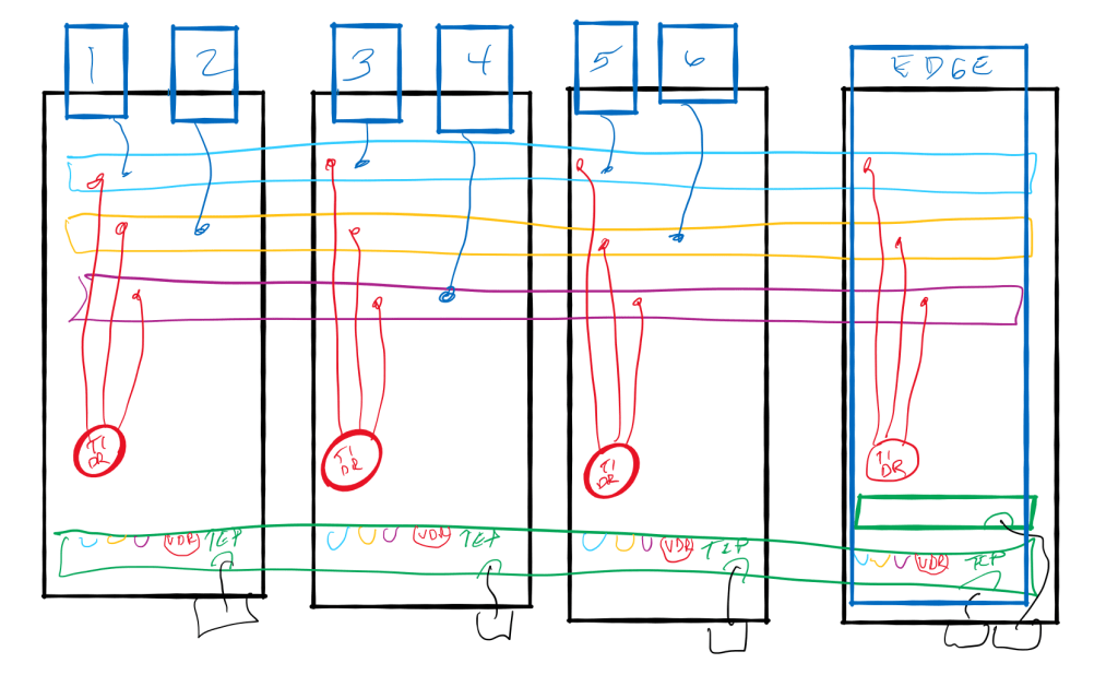
The magic of layer 3 happens on a hypervisor with a distributed gateway (DR) connecting to the segments on each hypervisor as well. This DR provides inter-segment forwarding through the use of that VDR port on the N-VDS. In this way communication between VM1 and VM2, for example, will not leave the memory space of the hypervisor on which they are each running.
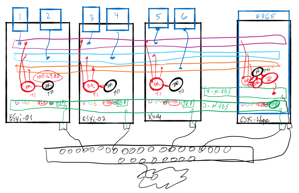
In the final (volume 2, number 3) video, I discussed the packet walks when using distributed routing and a service router (SR) component on an Edge Node cluster. I followed the path with an SR on the Tier-1 Gateway and without an SR, relying on the DR only for Tier-1 and using the SR of the Tier-0 for egress to the physical world.
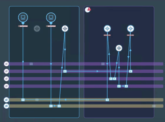
While the diagram came in handy for the initial discussion, a deeper discussion used VMware vRealize Network Insight (vRNI) topology path view to really describe the path between workloads with and without having the SR on the Tier-1. Two workloads on two segments will require a path to the Edge cluster if even one segment is connected to a Tier-1 gateway with an SR. In the video, I show the paths with and without the SR component on the Tier-1 gateway.
The conclusion I hope to pass along with both the video and this short blog, is that attaching a Tier-1 gateway in NSX-T to an Edge Cluster is necessary to support stateful services (Network Address Translation or Gateway Firewall, for example). If this Tier-1 gateway is not going to support these services, then it is inappropriate to assign an Edge Cluster to that gateway. That could have an unexpected impact on network traffic flowing in a “sub-optimal” path hair-pinning to and from the edge cluster when routing east-west traffic within the data center.
